Saturday 30 June 2012

Wheel Stud installation complete

I finished the wheel stud install. The fronts were, or seemed to be, easier to wind in than the rears, either because the front hubs are thinner or I had a more solid rig or a bit of both. Each stud took about 10 mins to wind in.

Notwithstanding the comment on the fronts being easier, I still had to use all my body weight to wind these in - partly because I couldn't get a longer spanner on the nut.
  • Squirt of WD40 in the hub hole
  • 7-8 Washers
  • Open ended nut on backwards packed with grease
  • Wind on one 1/2 a flat at a time
  • Take care to protect the threads on studs already installed with the spare nut

I thought the front hubs might have been hard to hold still, but a 1m long scrap steel bar with 10mm & 13mm holes in made the perfect jig for stopping anything moving.

The first 2 studs go on with a spare nut/bolt through a stud hole, centre boss stops anything moving:

The second two use existing studs and the spare wheel nut to anchor the steel bar, the bar is resting on the unthreaded part of the stud bottom right:

All Set:

Using the steel bar was a much better method than holding the hubs in the vice like I did with the rears.

For reference these are High Tensile Ford 12mm 1.5 studs, 47mm long, 13.1mm spline diameter (sourced from Mtec racing)

Friday 29 June 2012

Wheel Studs: 4 down, 12 to go

I'm using the washers + spare (open) wheel nut on upside down method to insert the wheel studs;

The downside is I can't get a socket over the nut this way up & therefore can't use a breaker bar:

4 down - 12 to go:

To be honest ,they are not all tight against the back of the hub, perhaps 1/4mm higher on some, they are as tight as I can get without the hub jumping out of the vice though. I'll have to re-check once wheels and a little driving has settled things in:
Double check the stud lengths with the disc & wheel in place, I have a good 10 full turns on the wheel nut until its tight:


Thursday 28 June 2012

Front ball joints, tap and fit


The M18 1.5 tap arrived so I cleaned out the nearside top wishbone.


 The balljoint thread is a good 60mm long, with about 50mm of that to wind into the wishbone - so I wound in the tap until it was past the fluting: WD40 to lubricate, then increments 1/2 turn forward, 1/4 turn back & repeat:

The original hole seemed to be clean for about 40mm, then either dirty or possibly no thread - its possible GBS don't tap this deeply enough.

I put together the front suspension - nothing fixed/permanent and IVA boots not in place - just really to see it setup:


Side panels will go on much later, when I have the engine mounts fitted - which means the front wishbones will also be removed at that point. I simply don't have the space to prep/mount the engine without getting to rolling chassis and being able to move the car out of the way.

Wednesday 27 June 2012

47mm Wheel Studs arrived, struggling to fit them

The wheel studs arrived - 47mm long, so I tried to fit some;

First brute force - hammer, then vice with a socket over the thread, then after cooling in the freezer. The first one is just vice + hammer, the second the same method after cooling in the freezer (not much difference):

At this point the vice was fine, however my bench & the vice mounting was moving, and I was at the limit of torque I could physically put into the vice.

Posted the query on RHOCAR - looks like the best option is to wind the studs in with an open wheel nut on upside down - Ordered same on Ebay. (arrived 29/6/12)

Tuesday 26 June 2012

Mostly on hold...

Waiting for parts:


1. Brake lines (fuel lines and loom)
Waiting for the master cylinder reservoir issue to be resolved.
I'm hoping GBS can come up with a solution for the sierra reservoir problem. Sierra reservoirs have completely dried up, so worst case I will need a new master cylinder from an Escort/Focus or Ka which may affect the brake line routing.

2. Suspension
Waiting for the 47mm studs to be delivered (arrived 27/6/12) & M18 tap to clean up the top front wishbones. I ordered the tap from Ebay at a good price - but its coming from Hong Kong. (arrived 28/6/12)

I really don't want to start on the engine changes until rolling chassis I want to avoid too many unfinished jobs on the go at the same time.

Possible jobs:

Bought a Dremel - so I may have a go at the nose & grill.

Fuel tank could be cleaned and fitted - provided it doesn't get in the way of completing the suspension.

Saturday 23 June 2012

Grille mesh fitting

The jigsaw, with metal cutting blade, I thought I would have a go at the stainless grille.
The cuts dont have to be acurate since I am mounting it from inside the nose with the intention of the nose opening dictating the grille shape, rather than the grille sitting on the front.

Damage:

The mesh is stronger than I expected & I managed to overheat a jigsaw blade in the process - infact totally melted down its teeth to smooth, along with the sweet smell of melting plastic coating.

Success:

Measure up, I only want to make 5 cuts; shorten the width and take each corner off:


Masked up so I don't scuff the good side:

Result:

Mocked up

It looks like I'll need to touch up the very edge of the nose with some red paint 
  -or- paint the recessed part black 
  -or- actually try and cut back the recessed part; 

Otherwise very pleased with the effect so far:

Target:

This is the sort of effect I am ultimately after - this pic is a Westfield, but the principle applies:


More under body seal & make ready for rolling chassis milestone

I have all the parts for the suspension now so getting near the point of dropping the car onto its wheels.

Underbody seal applied to the floorpans and underside of most chassis members, just the drivers side floorpan to go. The floor panels are stitch welded, so notwithstanding (or perhaps because of) the side panels overlapping this joint I am making sure any areas where water might sit have a  under seal coating and also running a bead of bond around the obvious joints inside the passenger area.


The garage is only wide enough for decent access around one side of the car so..

Next steps:

  1. Wait for 47mm studs to arrive & M18 tap
  2. Fully assemble the nearside suspension - uprights, discs, studs & calipers
  3. Shift the car to the other side of the garage
  4. Fully assemble the offside suspension - uprights, discs & calipers
  5. Install the steering rack & column
  6. Complete offside floorpan underbody seal
Then it should be ready to install the wheels and I can roll it out and make some space...

Wheel studs - 47mm needed

I have the stock team dynamics wheels from GBS.
I realised early on the standard 30mm wheel studs would be too short and before delivery of the kit bought the max 63mm studs from Mtec/Ebay.

Checked the wheels on discs & hubs today:
    30mm studs would give about 5 turns on the wheel nuts - not enough.
    63mm studs a going to foul the closed end wheel nuts

Turns out I need 47mm studs - subsequently ordered from Mtec racing.

Friday 22 June 2012

Front uprights and cycle wings

GBS came through with the replacement long bolt for the rear uprights and pinch bolts for the front uprights.

Straight bolts this time - the old one was like a banana and wouldn't go through the long bottom tube on the rear upright:

The cycle wing assembly needed a little cleaning up with emery paper by hand to remove the top surface/shine where it slides into the Sierra uprights. I also cleaned out the uprights themselves with a drum sander. Both went in fine, a little grease (hindsight: any grease might be a bad idea, these have to lock solid with the uprights) & one side with a little persuasion from a rubber mallet.


These parts are handed, with a notch on the offside/right side cycle wing bracket: (this is nearside so no notch):


These are not torqued up yet - I want the wheels/tyres in situe to line everything up before doing so.

Update (Feb 2013) - theres an interesting thread on RhoCar about making doubly sure this bolt doesn't come undone, I'm planning to upgrade this pinch bolt to take a nyloc on the end & a couple of roll pins 'belt and braces' so the dummy shaft cannot pull out of the upright see Here

Thursday 21 June 2012

Removable spare wheel/luggage carrier

I had the chassis altered in manufacture to accommodate a removable spare wheel carrier. GBS did a great job - the only thing I would have done differently is thread the lower rather than upper holes. I am going to bond a couple of steel stainless + painted washers (steel over the hole to block it & painted to avoid any reaction with the ally fuel tank) between these holes and the fuel tank which sits above to avoid any possibility of a long bolt puncturing the tank.

It seems everyone does without spares on sevens, but it just feels wrong to me - so I hedged my bets, this carrier can be removed relatively simply if I end up doing track days or dually serve as a luggage rack. 

This will take the weight, and only need a threaded rod/securing cable and lock from the centre of the wheel through a hole in the back panel to secure it:


It is entirely within the height of the rear tube, so will need only a couple of holes in the back panel & will let me add a diffuser, which mounts flush with the underside of this chassis bar, in due course:

Propshaft

Thinking about assembly sequence, I offered up the propshaft and its tight to get the flange through the chassis. It might even be impossible to do this with the gearbox in situe. I get another benefit, the diff cannot move fore/aft so now with the propshaft in this gives me a datum for the gearbox input shaft fore/aft:

Double checked the diff flange bolt torque, then bolts/threadlock and torqued the four prop shaft bolts. I used the steel bar from my vice to lock the UJs in place to tighten everything.


Later pictures, I hung the shaft from the frame & covered the end with a rag - as the car is moved about it all moves & this just stops it banging/clanging around the chassis until I install the gearbox.


On the gearbox it is roughly 9.25" from the bottom mount point to the output shaft, and roughly exactly the same distance if the mounting rubber is centre/slightly front of centre on the chassis.

I am therefore delaying installing the gearbox mount rubber until I have measured this properly or possibly actually offered the gearbox into position: Turns out its fine - I later decided to install the mount rubber centrally & didn't run into any problem fitting the gearbox later.

Wednesday 20 June 2012

Grille mesh arrived

I was intending to buy the GBS Jag style grille mesh, and nearly did at Newark - unfortunately GBS still have some significant items left to deliver on the original kit order so decided to wait until all square with them before putting more on the account.

In the meantime I looked around for options - Zunsport (via Ebay) sell the basic mesh at a hugely discounted price over the GBS offering. GBS is fitted/trimmed etc to sit on the outside/front edge of the nosecone which I cannot compete with. My intention is to cut the rectangle of mesh I have and fit from the inside - i.e. I should get a nice clean/neat edge from the exterior view.

I'm thinking a a couple of cable tie bases bonded in the nosecone at strategic points then cable tie it in place should do the trick.

These pictures don't do the grille justice, but I'm not taking it out of thre bag yet: 540mmx230mm sheet is perfect for the Zero nose:

Its powdercoat or plastic coat over stainless steel wires:

Template from the nose:

I will only need to trim the sides a little and take the corners off, since I am mounting from the inside the nose itself will make it look tidy. This isn't as bad as it looks vertically, since there is a lip on the inside of the nosecone it actually overlaps a good cm or so. I will leave 2-3 times that on either side to cable tie it into place.

Minor problem:

I can't cut it :) ..  pliers & nibbler aren't the right tools, hack saw vibrates too much. I think it needs a rotary tool - I'll see if I can borrow one.

Tuesday 19 June 2012

Hand brake

GBS came through with the handbrake kit which I picked up at Newark.
Handbrake mounted, and cabling roughly in place:

I still have the R clip on the handbrake crescent on top here - later I changed it, pin through from the top with washer and R clip on the bottom so gravity is holding the locating pin in place too.

The cable should also be attached with the top hole in the handbrake, i.e. to give maximum leverage


Clearance for the brake line 4 way above the handbrake cable is tight. Currently I have the 4 way mounted in the existing chassis hole. This is probably why it comes with a rivnut and bolt & will probably get mounted about 5mm higher in due course.

Revised route for the handbrake cable, copied from various other blogs, low around the hub and under/between the arms of the top wishbone. There is a P clip to install somewhere near where my thumb is - but probably not going on until I have the offside mocked up too:

Seatbelt mounting threads

My 7/16ths tap arrived from Ebay this evening, so cleaned out the seatbelt threads.

WD40 to lubricate, care/paranoia about cross threading the tap, and an adjustable spanner cleaned them up nicely. The inboard ones seemed to be heavily powder coated, this process seems like a must process rather than an option:

Before:

After:

I only need 2 taps for the project, this one and one for the front top balljoints, so no full tap kit. Adjustable spanner has to do. Half turn forward, quarter back & WD40, taking it slooow:

Inboard mounts clean:

Sunday 17 June 2012

Rear uprights - reversed the bolts

Much better - bolts reversed with the nuts inboard.
The 50mm bolts actually just fit in behind the hub, or would pass through the large holes in same so there should be no problem dismantling (if required) once everything is assembled.

All torqued up:


Rear hub/calliper & brake line

Before fixing the hand brake cable I wanted to understand the route; so decided to fit one of the half shafts, hub assembly.

This let me understand how the brake bracket fitted, which way round to put the hub bolts etc.  None of this is torqued up yet - purely done to understand layout, the caliper has to come off anyway to fit the disc, pads & to be bled.

Rear Brake hub/caliper fixing:

Worked out from other blogs the order from inboard to out is:
  1. Zero rear upright
  2. Zero caliper mount bracket - flat side inboard
  3. Shaft hub
  4. Calliper on upside down - otherwise there is no route for the handbrake cable
The shaft CV joints will compress to allow this to go together & the bolts are just long enough to get a nut on before tightening them up a little each and pulling everything snuggly together:

I decided to put the bracket bolt heads inboard, and nuts outboard - this means

  1. I could place the bolts in the holes and push on the hub/bracket assembly just enough to get a nut on before tightening it.
  2. I can remove them without having to remove the hub nuts & once the hub nuts are finally tightened they are never coming off - thought - thats what the big holes in the wheel hub are for! - inserting the bolts.
Addendum:
The more I look at this, bolts inboard, nuts outboard - the more I dislike it, looks nasty - I'll be swapping it round I think...

Update - when changing and maintaining the bearings the nuts will be going back on the outside - much easier to get a spanner to on a built up car!

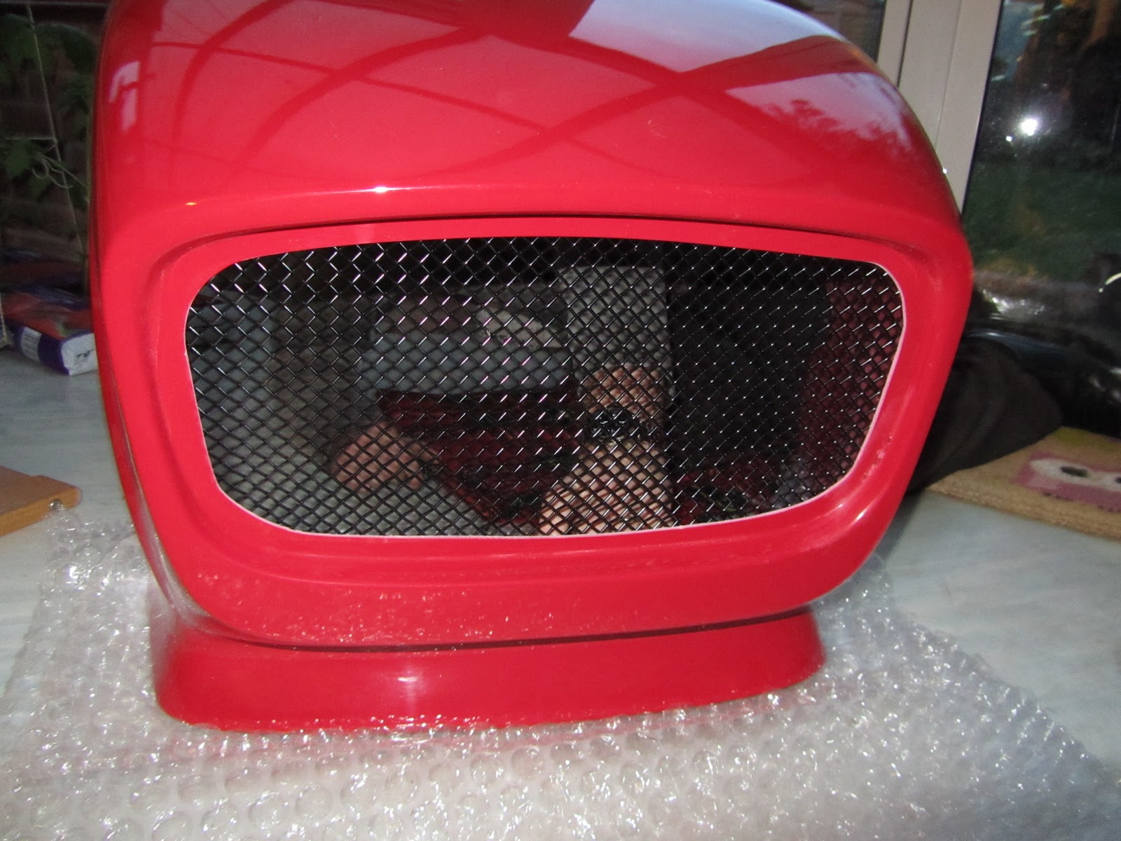
 Identified handbrake cable route, The P clip will sit on the rear upright:

Addendum:
The cable will actually route lower than this and go under the top wishbone arm in the picture.


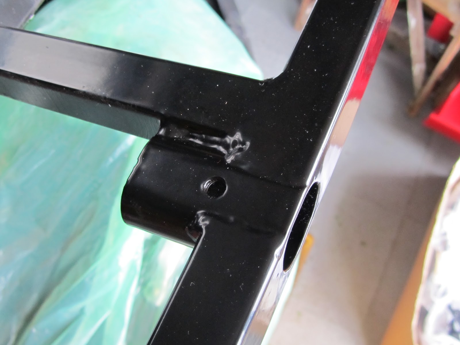
Everything in situe - I used the original old hub nuts to pull the hubs back onto the shaft splines, I have new hub nuts when I'm sure this isn't coming off again - I dont know if I can get the wheel studs back into it while assembled like this (should have thought of that earlier :) )
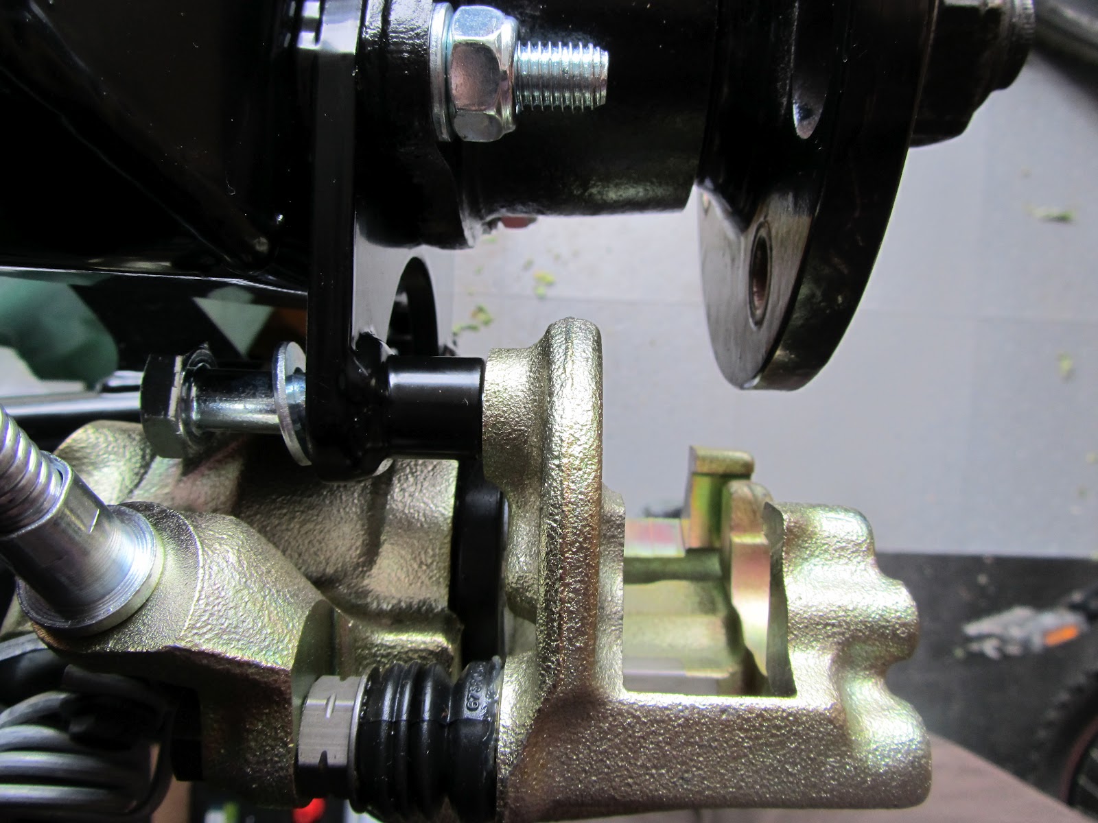
Caliper bolts:

My kit had a bag marked 'rear calliper' which contained 12x M10x50 bolts/washers/nylocs - the rear callipers need 2xM10x40(ish) bolts.

50mm is definitely too long - they would foul the disc, I cut down a couple of the 50mm bolts to 40mm , I might re do it a couple of mm longer to allow for the washer. These bolts will be threadlocked in, I need to decide if they need a locking/shake proof washer too.

This 50mm if tightened would emerge from the other side of the calliper:

Note this was re-worked with locking washers behind the bolts and slightly longer 43mm bolts Here


2mm longer at 42/43mm total would have been perfect -or- do without the washer These need a locking washer & will be re-fitted later.


Due to the mystery 12x nuts/bolts bag I am only short some M10 washers now - might be due to my habit of placing a washer under the head as well as the nut of every bolt :)