Emerald K6
Zetec 2.0 (2004), GBS Plenum, OEM Fuel pressure regulator
All settings current from 6th April 2018
Settings changed since then - need to get around to a new update after the MOT - changes to AFR target, Injection, TPS load sites all sorts of fun :)
Extra Pin outs
Pin 03 - IACV PWM control output
Pin 06 - Engine cooling fan relay control output
Pin 07 - Narrowband input (not used)
Pin 10 -
Pin 18 - Lambda signal ground
Pin 20 -
Pin 30 - Sensor earth
Pin 34 - Wideband Lambda signal input
Pin 35 - Map switch input


Events / Switches
Shift light and rev. limiter moved to be relatively conservative, shift light at 6k rpm, cutoff from 6.5k.
Map Switch
Set to give me a 2.5v range for Map 2, and 1.25v to the stops for the other two maps.

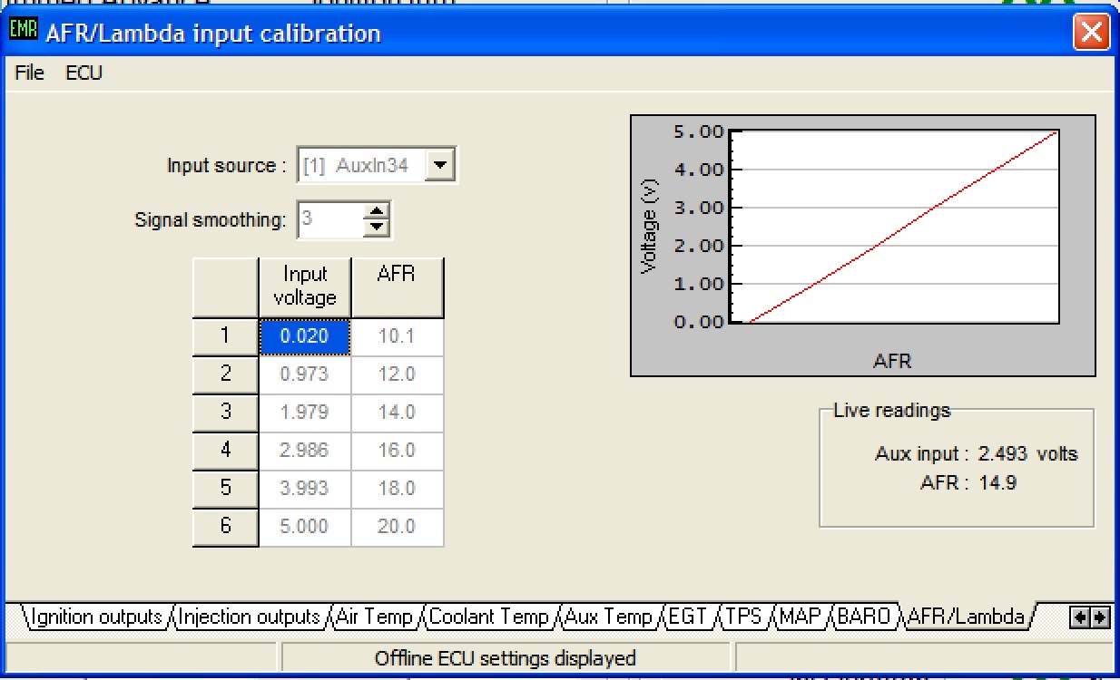
Lambda Sensor
Wideband 14Point7 Spartan2 sensor/controller.
The sensor configuration using my customised 14Point7 wide-band calibration spreadsheet which provides voltages adjusted to 6 data points. Double checked after the power feed changes and its still spot on - so at least the Spartan2 is completely independent of supplied voltages for an accurate reading.
Turned out there was a small error in my spreadsheet which I think was leaning me off by about 0.1 AFR. TBC after the MOT.


Some changes pending on the idle/750rpm cell and high temp compensation to come.


Adjusted with extra resolution around idle - a full column at 850rpm to help stabilise the idling area.
Fuelling adjusted in the MOT testing areas - 1k and 2.5k revs to ensure the Lambda can adjust fuelling and not up to its stops.

The sensor configuration using my customised 14Point7 wide-band calibration spreadsheet which provides voltages adjusted to 6 data points. Double checked after the power feed changes and its still spot on - so at least the Spartan2 is completely independent of supplied voltages for an accurate reading.
Turned out there was a small error in my spreadsheet which I think was leaning me off by about 0.1 AFR. TBC after the MOT.

Lambda coolant enable set to kick in as the cold-start injection corrections stop around 70º, gain and frequency adjusted so the mixture settles and doesn't overshoot too much.

Re-introducing some acceleration at lower throtle position, 15's in the overrun area.
Low revs closed loop area for 14.7 (calibrated) MOT idle area, fast idle may follow once the AFR adjustments settle in.
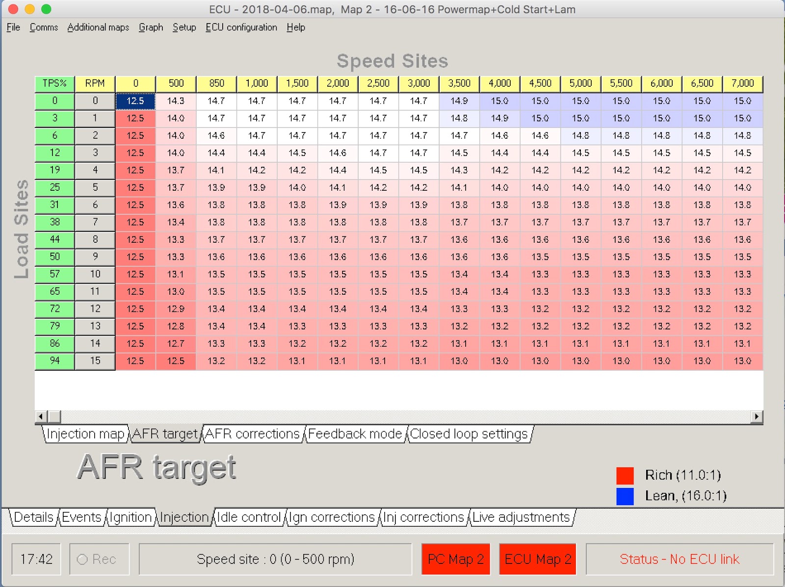

The secondary map varies only in the AFR targets being closer to the original GBS power map.


Ignition
These have never been touched- pretty much as they were on the original GBS Power map.Some changes pending on the idle/750rpm cell and high temp compensation to come.


Injection
Now running semi-sequential - on advice from Emerald. As I understand it this means the fuel is injected into the inlet more in sync with the inlet valve cycles, so less time sitting there for half of the four stroke cycle.

Adjusted with extra resolution around idle - a full column at 850rpm to help stabilise the idling area.
Fuelling adjusted in the MOT testing areas - 1k and 2.5k revs to ensure the Lambda can adjust fuelling and not up to its stops.

Battery compensation curve shape altered and levelled off between 13.5 and 14.5volts to stop significant changes in injection at idle speeds due to the alternator fluctuations at low revs.

IACV & Idle Control
OEM Ford Inlet air control valve from the Zetec inlet manifold.
Position will depend entirely on the IACV's particular air path - I recently opened up and flattened off the curve on some of the higher temperature settings, this seems to let the engine run more stably at tick over.


Target idle adjusted for 1,000 revs minimum:


Cold Starting
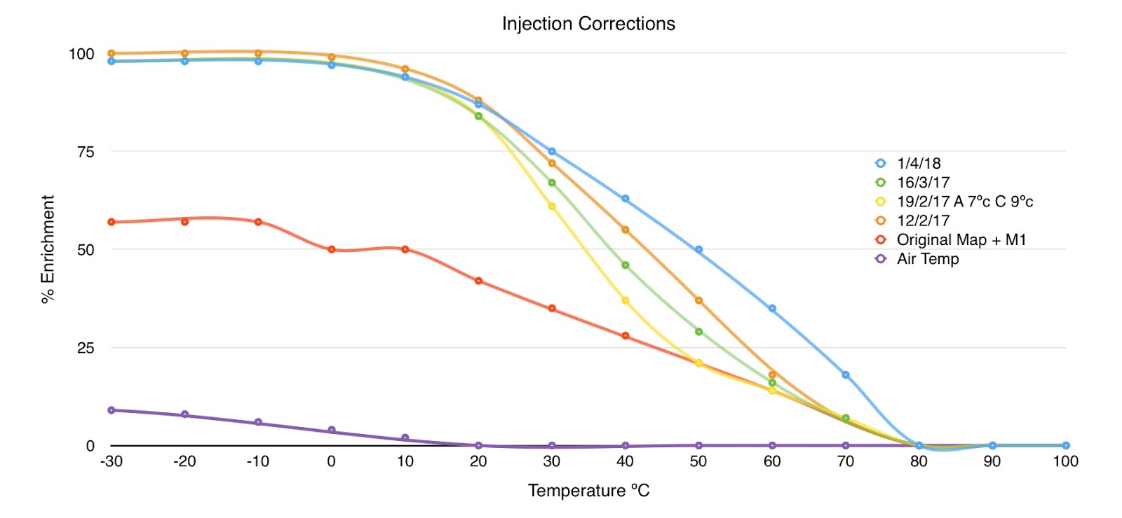
Adjusted across the board for higher initial prime then a smooth curve for the enrichment table on 2 to 120 turns. Air temp compensation is not adjusted.
Missing the Air Temp compensation for 60º+. To be updated, this was masking any adjustment I did in the garage where air temp was rising on long idle test runs. Meant the next start/check from cold was too lean.

I'm graphing the my cold start test/adjustment runs so I can visually sanity check the curves being produced. The biggest impact on cold starting appears to be the initial prime to get things moving.

Missing the Air Temp compensation for 60º+. To be updated, this was masking any adjustment I did in the garage where air temp was rising on long idle test runs. Meant the next start/check from cold was too lean.


Then the injection correction kicks in until things warm up blue line at the top is the current setting.
Another excellent report from the Zero Research and Development Unit.
ReplyDeleteIf only I could understand it without having done it. Cheers Graterham