
Its Sunny !
The British summer turned up and the weather has been good for driving, so while there are over 800 miles on the clock now I've made no progress on the roof.
Reminds me of an old cartoon in my favourite childhood book: Story Book Dictionary -now- Best Picture Dictionary Ever by Richard Scarry.
One of the Busy Town animals has a large hole in his roof:

Wow - just thought - theres my '80/20' rule or 'Good enough' lifestyle choice right there - learnt probably before I was 5 years old ha!
Digital Speedo Circuit Design
The circuit itself is cribbed from a number of forums existing projects etc & I found some great online tools for checking & drawing circuits:
Circuit Lab allows full simulation over time & 30 day free trial
Digikey Scheme It allows diagramming for free\
My current circuit intention is something like this:

S1,S2 - Front panel momentary select & reset buttons
R1,R2 - 5k6 pull-ups for the I2C bus
R3,R4 - 10k pull-downs on the switch inputs
R5,R6 - 200R current limiting on the 12v sensor inputs
D1,D2 - 5.1V voltage limiting Zener Diodes on the 12v sensor inputs
Mocked up currently looking like this:
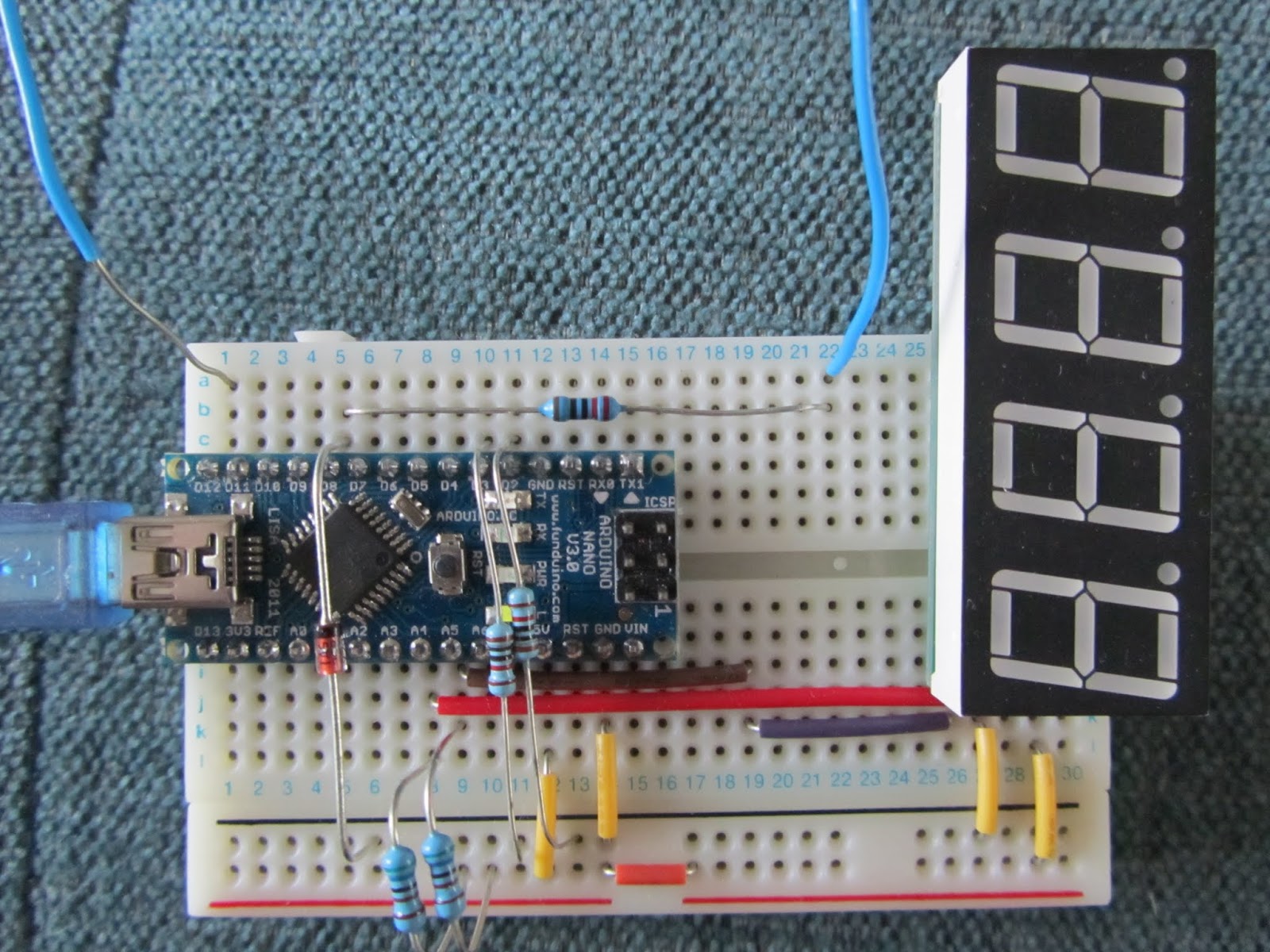
+5v will be via a solid state regulator to drop me down from the car's 12v line
Inputs are 12v current and voltage protected with resistors & Zener diodes.
The illumination input will be to turn the brightness down rather than up - i.e. when instrument illumination is on its dark outside so I want to avoid glare from the LED display; not yet even mocked up.
How long does debugging take...
Its been a while since I coded anything, its pretty good fun though;
I think I read somewhere (I could have the numbers completely wrong) you can write about 4 lines of bug free code a day - not through slow typing, just because debugging takes time. Arduino tools are pretty basic too, the debug cycle is to embed print statements in the code, download, run, monitor the serial output - no single stepping :/
Some progress though - the project has expanded & I now have basic menu code working for functions with two input buttons: select & reset. The functionality will be:
- Speed - to 10ths of MPH
- Selectable speed warnings at 30, 50 & 70 mph
- Trip 1 & 2 - to 100ths & 10ths of a mile respectively
- 0-60 timer - starts when the car starts moving or red button pushed
- 1/4 mile timer - starts when the car starts moving or red button pushed
- Calibration - on the fly tweak speed up/down & entry of pulses per mile - could even drive this via the USB/Serial input i.e. console base calibration.
- Sense instrument illumination to adjust brightness
I'm trying to tidy up the timing code for measuring speed based on the time between bolts passing the speedo sensor but its been hit & miss without a proper function generator to test it. I have this rudimentary pulse generating code creating an output on one pin which I feed back into the sensor pin - hence that flying wire on the picture above taking the output back to the sensor input.
Unfortunately - up to a point - I am a perfectionist with code, keep tinkering, re-arranging, checking until it both works and looks pretty.
Update - the digital speedo is on hold until the dash next comes off and I add circuits - which wont be while the weather is so good!
Update - the digital speedo is on hold until the dash next comes off and I add circuits - which wont be while the weather is so good!
No comments :
Post a Comment